Vẽ ý đồ, để máy thử phần còn lạiDraw the intent, let the machine try the rest
- AuthorTác giả
- Đặng Văn Dũng
- DateNgày
- ReadingĐọc
- 10 min10 phút
- KeywordsTừ khoá
- LanguageNgôn ngữ
- VI · EN English version ↓
Một cách phân chia vai trò giữa kiến trúc sư và máy trong thiết kế đô thị: ý đồ thiết kế được vẽ và giữ cố định, máy chỉ khảo sát các biến được mở, rồi trình bày các đánh đổi để kiến trúc sư lựa chọn. Bài kèm một bản minh hoạ chạy trên trình duyệt.
A division of roles between architect and machine in urban design: the design intent is drawn and held fixed, the machine explores only the variables left open, then presents the trade-offs for the architect to choose. The post includes an illustration that runs in the browser.
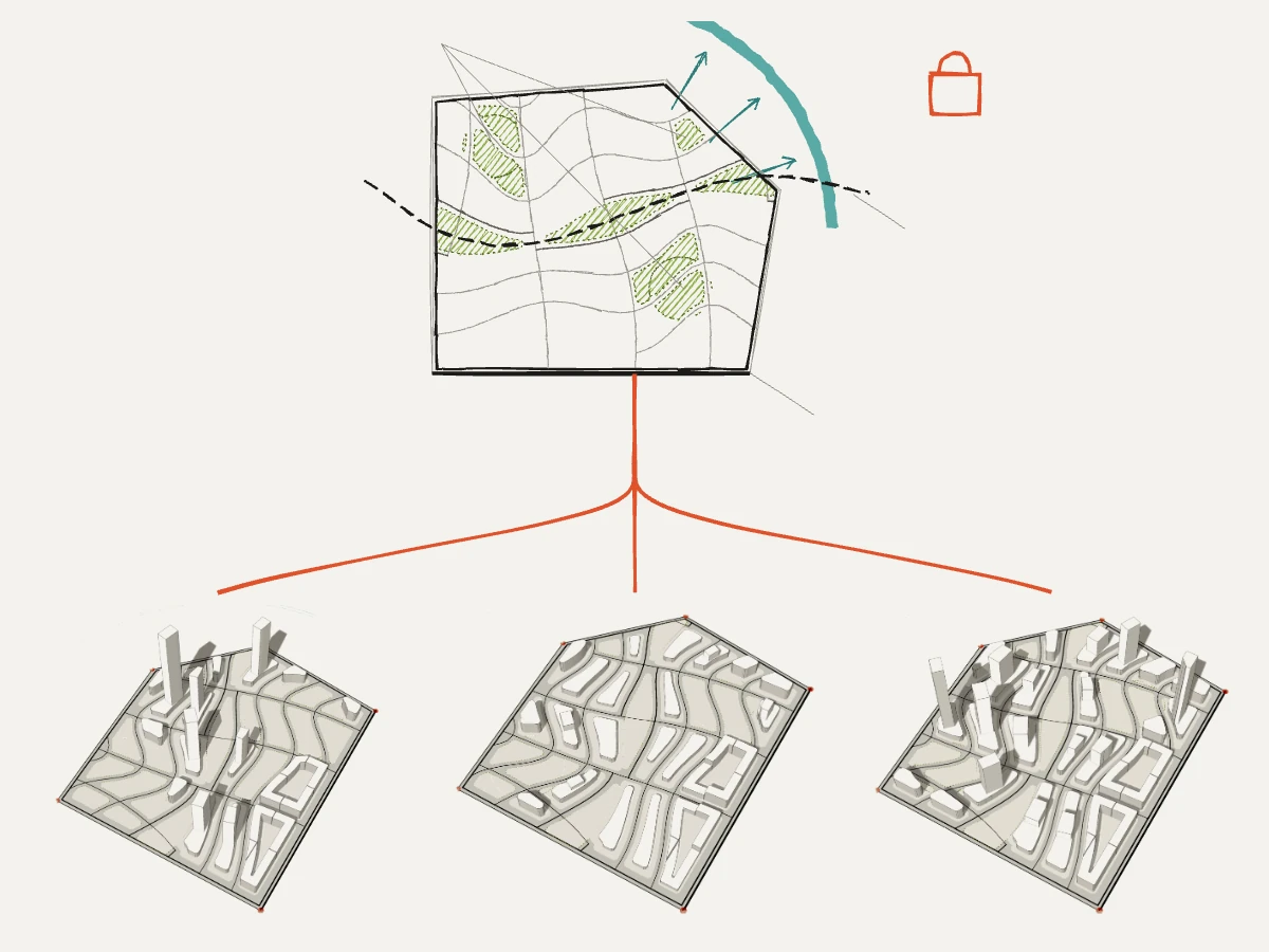
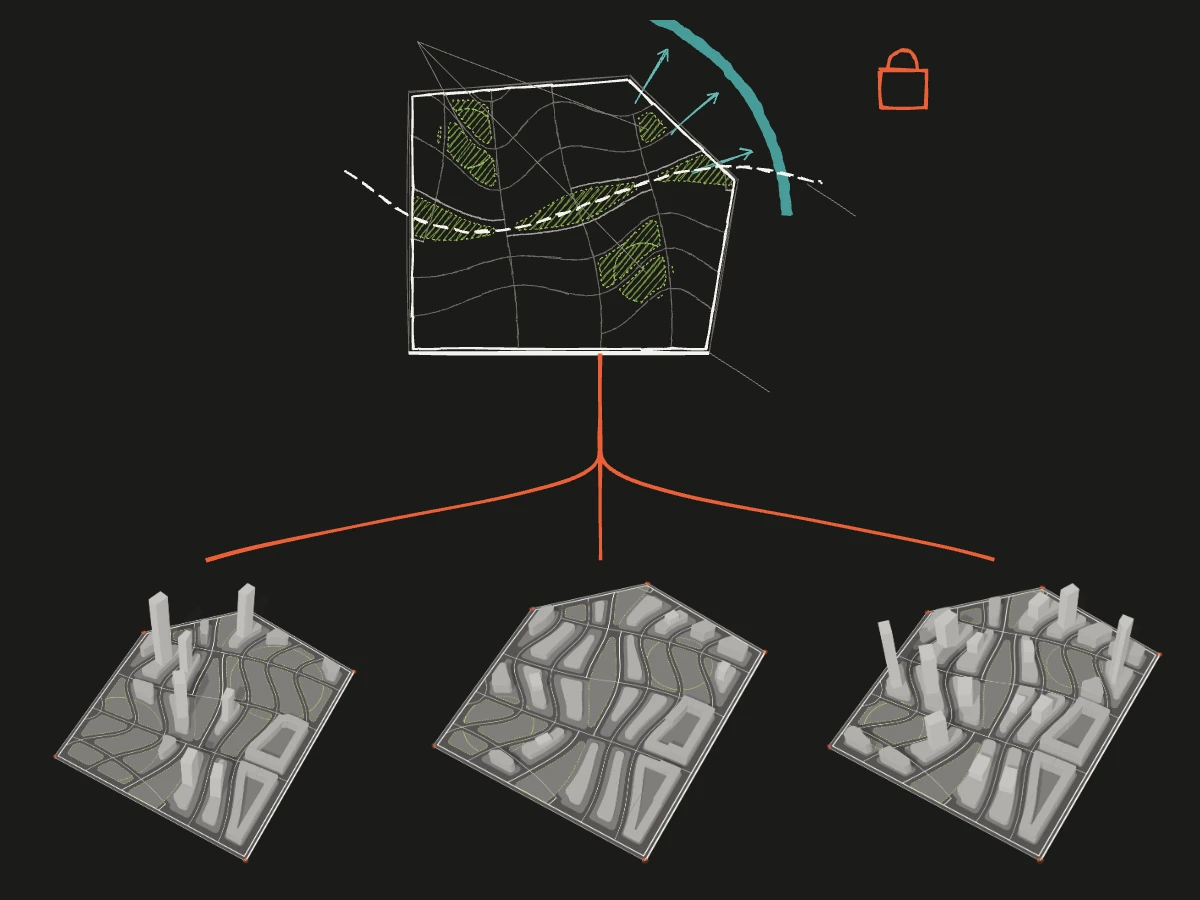
Kiến trúc sư vẽ và khoá ý đồ · máy thử các biến được mở · mỗi phương án kèm điều nó đánh đổi
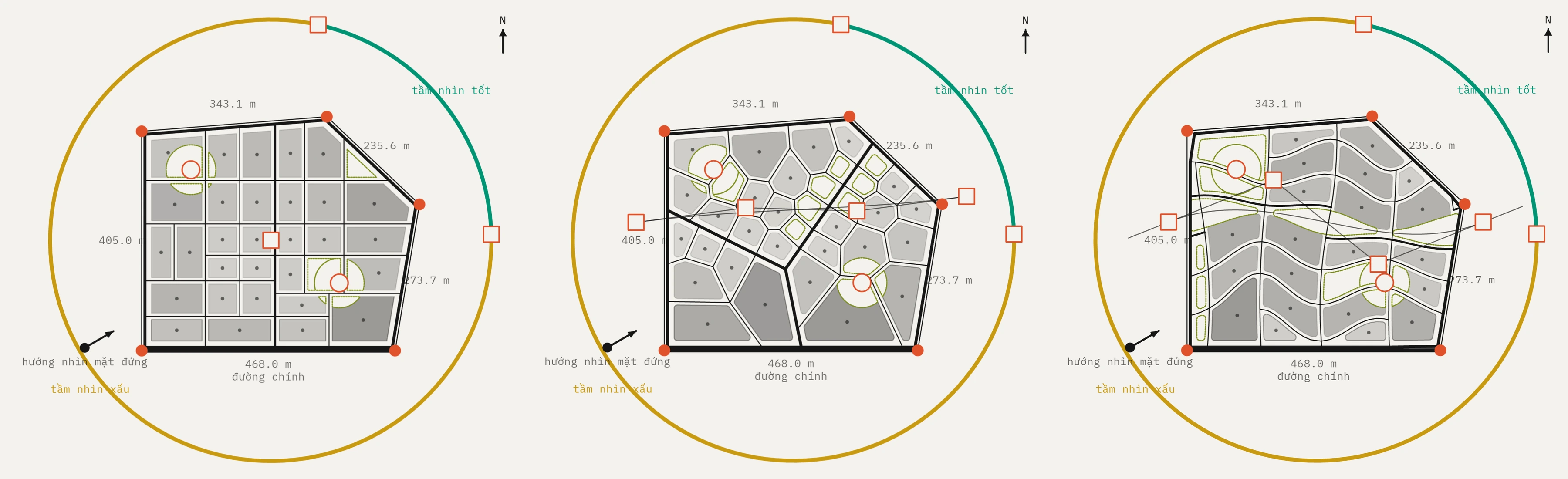
01 · Vùng khoá · phác ý đồ của kiến trúc sư
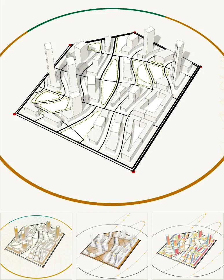
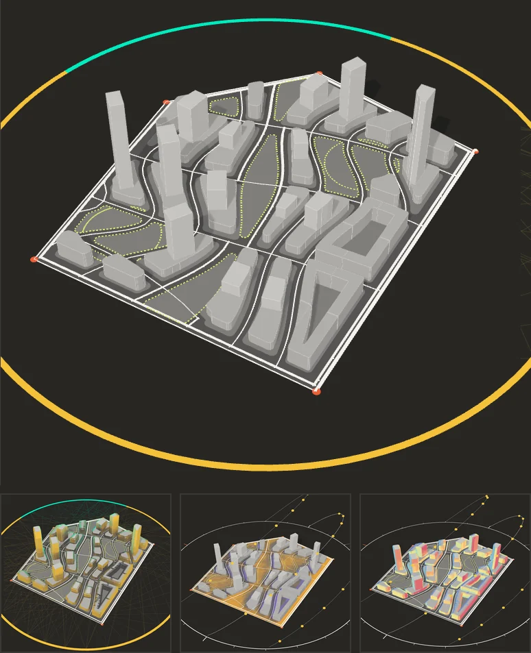
02 · Vùng mở · máy thử chiều cao tháp, mảng xanh, mật độ đế · một lượt chạy, ba góc của tam giác đánh đổi
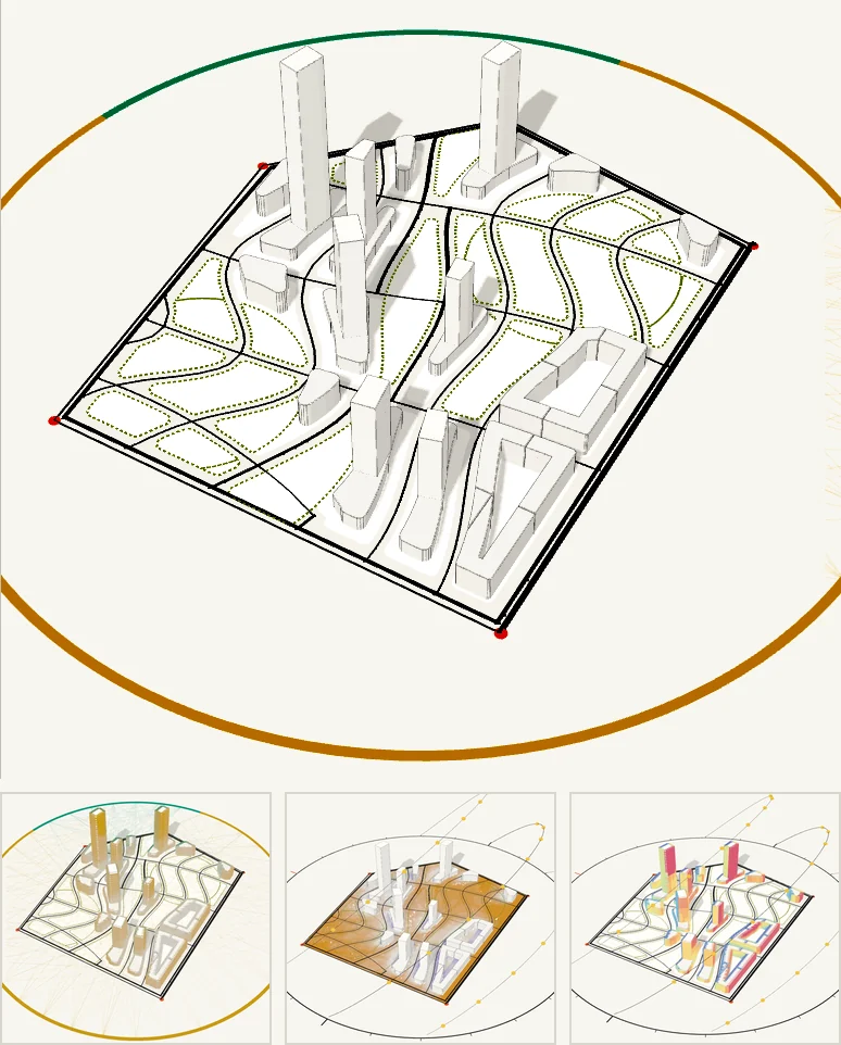
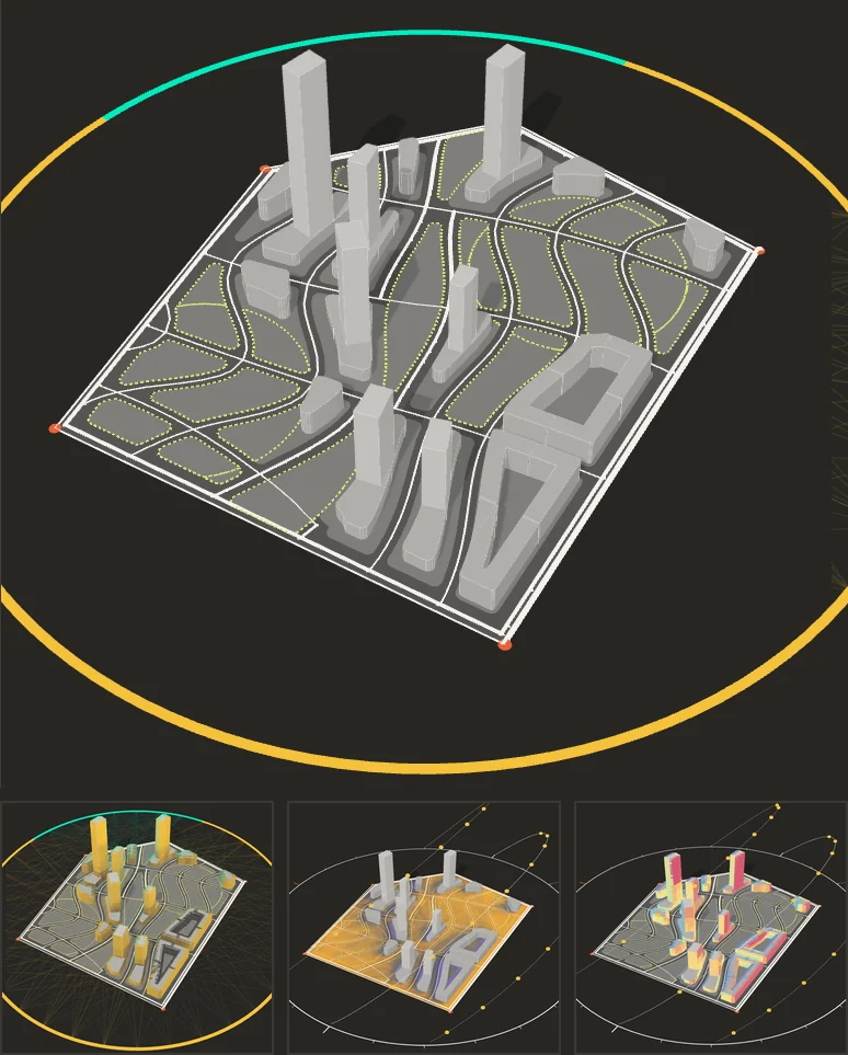
Tầm nhìn tốt nhấttháp 191 m · đế 43 % · xanh 38 %
- GFA
- 260.763 m²
- tầm nhìn tốt
- 52,9 %
- sáng mặt đứng
- 77,3 %
- lệch GFA
- 36,4 %
Sáng mặt đứng nhấttháp 40 m · đế 42 % · xanh 21 %
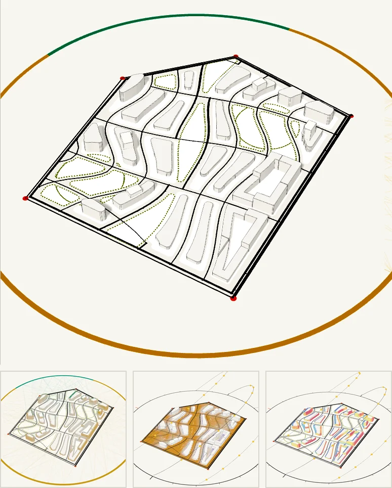
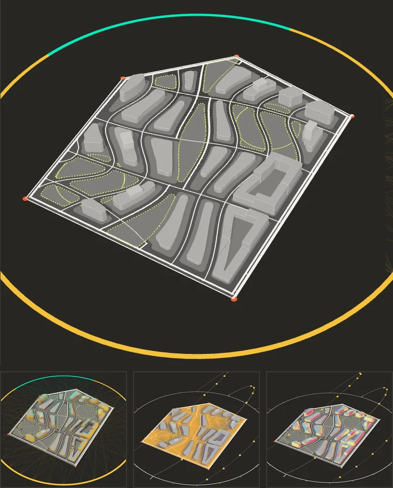
- GFA
- 156.455 m²
- tầm nhìn tốt
- 41,3 %
- sáng mặt đứng
- 87,1 %
- lệch GFA
- 61,8 %
Sát GFA đề bài nhấttháp 158 m · đế 62 % · xanh 17 %
- GFA
- 409.438 m²
- tầm nhìn tốt
- 37,4 %
- sáng mặt đứng
- 71,8 %
- lệch GFA
- 0,1 %
Trong thiết kế đô thị, nhiều quyết định nền tảng khó định lượng: hướng của mạng lưới đường, hình dạng đường chân trời, vị trí các mảng xanh. Phương pháp thủ công tạo được ít phương án, và tầm nhìn, bóng đổ, bức xạ mặt trời thường chỉ được đánh giá ở giai đoạn cuối. Ngược lại, công cụ tối ưu hoá tự động quy mọi yếu tố thành biến, khiến ý đồ thiết kế khó được kiểm soát. Bài viết đề xuất một cách tiếp cận ở giữa: kiến trúc sư giữ ý đồ, máy chỉ khảo sát những gì được mở.
Chúng tôi đề xuất gì
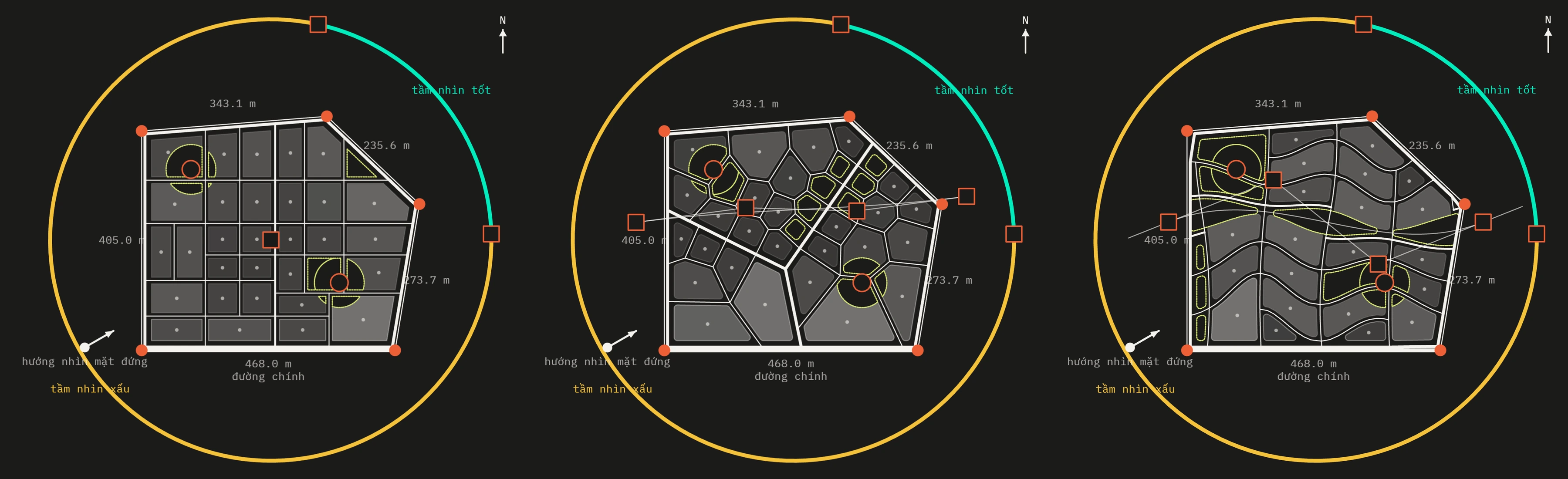
Cách tiếp cận tách hai loại quyết định. Ý đồ thiết kế gồm lưới đô thị, đường chân trời và vị trí mảng xanh; kiến trúc sư vẽ và khoá chúng. Các biến thiết kế gồm chiều cao của tháp cao nhất, tỷ lệ mảng xanh và mật độ xây dựng của phần đế; kiến trúc sư đặt khoảng cho từng biến, máy tìm kiếm trong các khoảng đó. Hệ số sử dụng đất là kết quả của các biến này, không phải một biến. Kiến trúc sư cũng quyết định máy đo phương án bằng những mục tiêu nào và theo chiều nào, tối đa hay tối thiểu; một số mục tiêu phụ thuộc vùng khí hậu, nên chiều của chúng được chọn theo khu vực của dự án: nắng trực tiếp trên mặt đứng nên được giảm ở vùng nóng ẩm, nhưng có thể nên được tăng ở vùng lạnh.
Phần việc của máy đi qua bốn khâu: sinh hình, đánh giá, tìm kiếm và lựa chọn. Mỗi khâu là một khe có đầu vào và đầu ra xác định, nên có thể thay bằng công cụ khác, từ một script tự viết, một plugin của phần mềm thiết kế đến một dịch vụ mô phỏng. Khâu lựa chọn trình bày các phương án đánh đổi, tức các phương án không bị phương án nào khác vượt trội ở mọi mục tiêu, để kiến trúc sư quyết định.
Bản minh hoạ
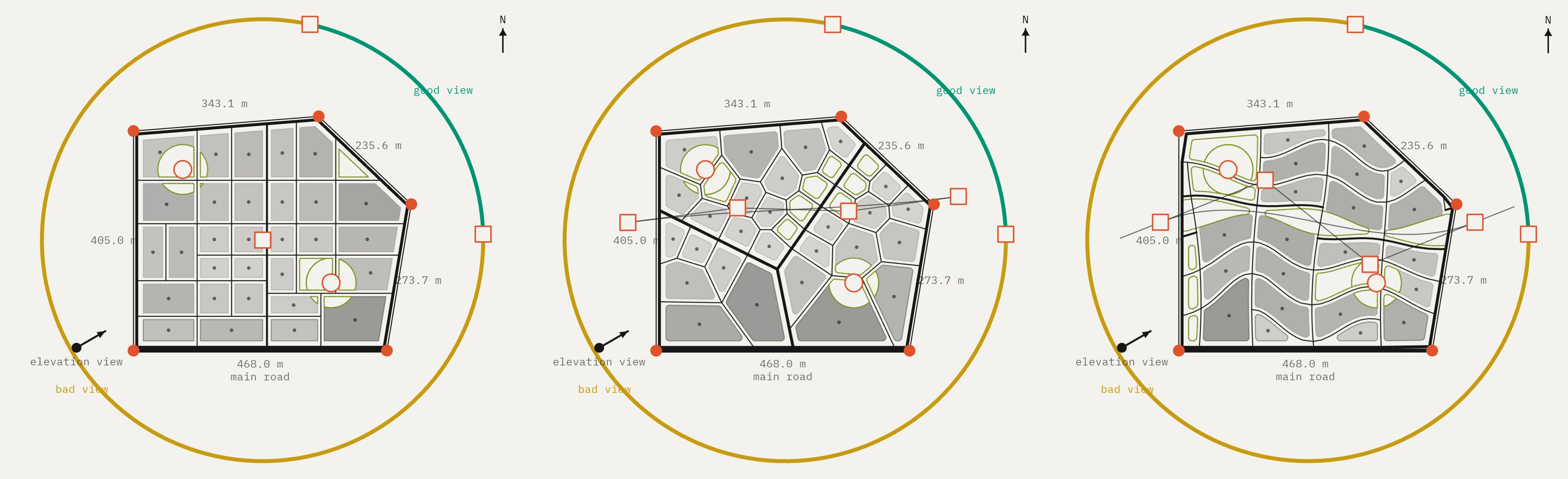
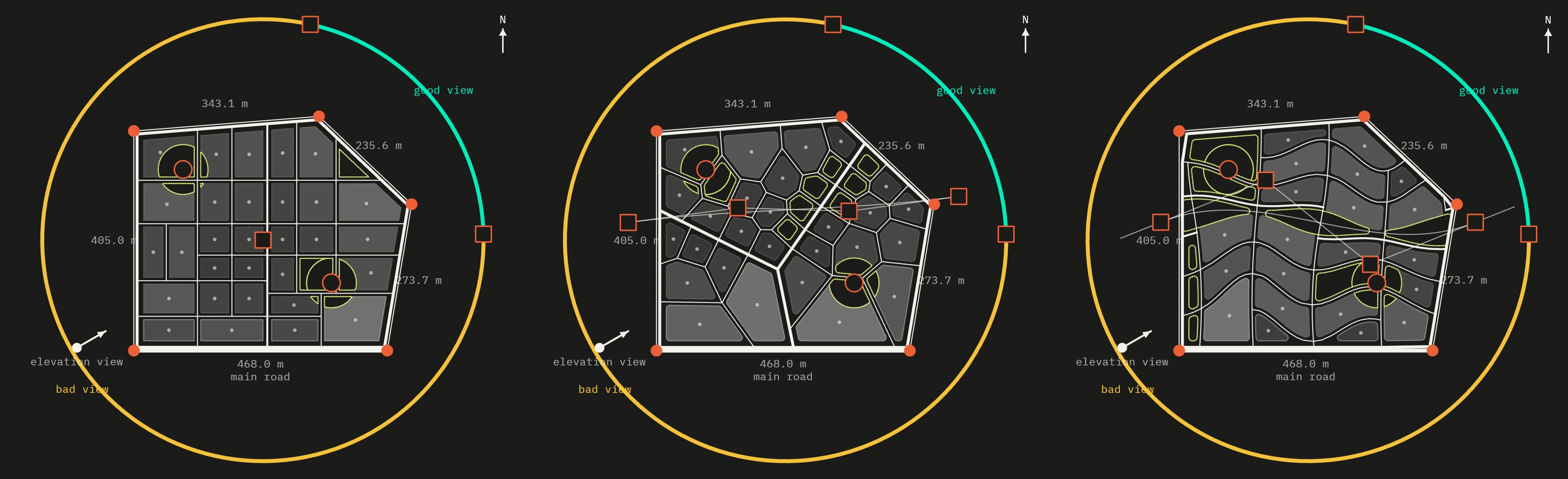
Để minh hoạ, chúng tôi dựng một trình mô phỏng chạy trên trình duyệt, trên một khu đất giả định. Đây không phải công cụ làm việc cho dự án cụ thể, mà là mô hình thu nhỏ để người đọc thử cách phân chia vai trò nêu trên. Ở bước Thiết kế, người dùng vẽ ý đồ: ranh khu đất, kiểu lưới đô thị, mảng xanh, đường chân trời và cung tầm nhìn tốt. Ở bước Đặt giới hạn, người dùng đặt khoảng cho ba biến và tổng diện tích sàn của đề bài; ý đồ được giữ nguyên, chiều của các mục tiêu được đặt sẵn. Ở bước Chọn, bốn thẻ đặt cạnh nhau ba phương án gần mỗi góc của tam giác mục tiêu nhất và một phương án cân bằng; toàn bộ các phương án đánh đổi vẫn xem được trên biểu đồ ba trục và trên các tam giác, và có thể ghim tối đa bốn phương án để so sánh cạnh nhau.
Khâu đánh giá gồm ba mục tiêu:
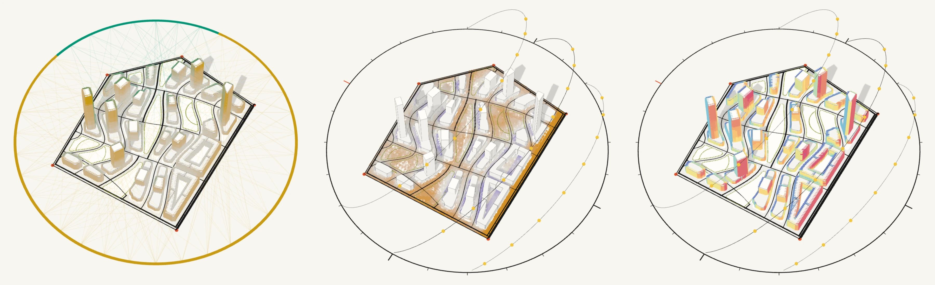
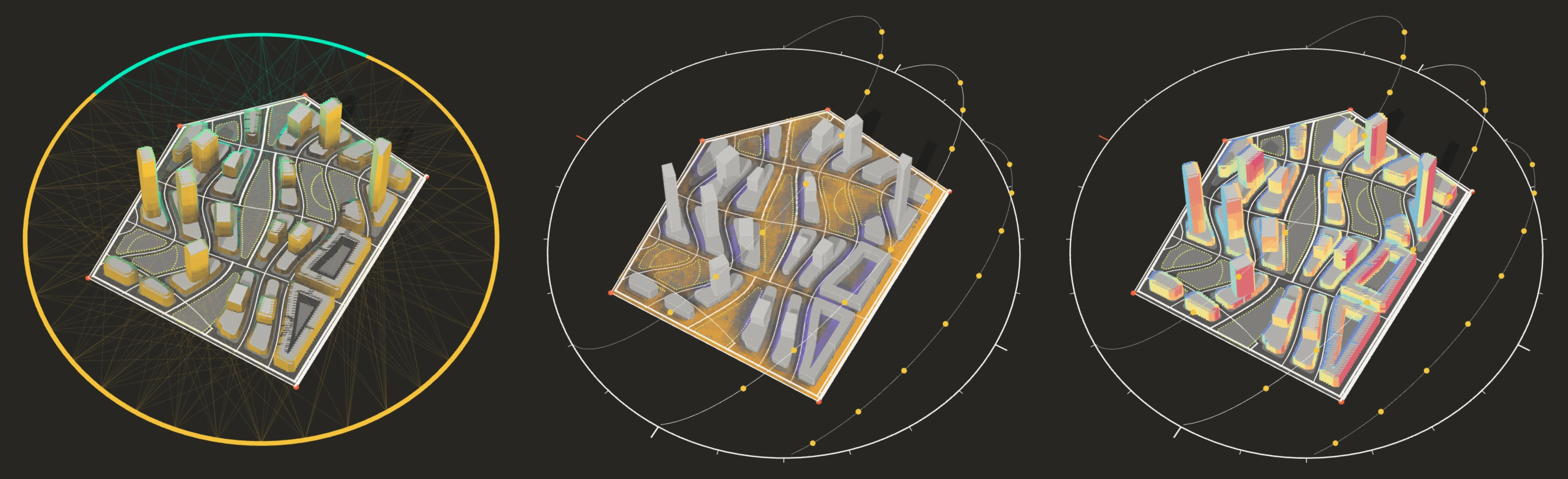
- Tầm nhìn tốt: tỷ lệ mặt đứng nhìn thấy cung tầm nhìn tốt mà kiến trúc sư đánh dấu trên một vòng quanh khu đất. Như vậy, ngay cả tiêu chí "tầm nhìn tốt" cũng thuộc ý đồ thiết kế.
- Ánh sáng trời trên mặt đứng: phần bầu trời phía trước mỗi điểm đo trên mặt đứng không bị công trình nào che, tính trung bình trên các điểm đo. Đây là một chỉ số tương đối, gần với thành phần bầu trời trên mặt đứng (vertical sky component), không phải hệ số chiếu sáng tự nhiên. Tháp càng cao, tầm nhìn càng rộng, nhưng các mặt đứng càng che bầu trời của nhau; mục tiêu này vì vậy ngược chiều với tầm nhìn.
- Độ lệch so với tổng diện tích sàn của đề bài: phần thiếu hoặc thừa so với tổng diện tích sàn kiến trúc sư đặt cho đề bài. Diện tích sàn vì vậy là một yêu cầu cần đáp ứng, không phải một đại lượng cần tối đa.
Tầm nhìn và ánh sáng trời trên mặt đứng được tính bằng phương pháp dò tia trên khối công trình. Để đọc từng phương án, bản minh hoạ còn hiển thị bóng đổ trên toàn mặt đất và mức phơi nắng trực tiếp trên mặt đứng (chỉ số tương đối, không quy đổi ra kWh/m²); hai lớp này không tham gia tìm kiếm. Một dự án cụ thể có thể cần chỉ số khác; khi đó chỉ khâu đánh giá thay đổi.
Một tác nhân lập trình AI (Claude Code) viết mã sinh lưới, dựng khối, đánh giá, tối ưu và kiểm tra tự động; kiến trúc sư đặt câu hỏi, chọn hình thái lưới, quyết định yếu tố nào thuộc ý đồ và phê duyệt từng bước. Cách phân chia vai trò khi phát triển vì vậy tương đồng với cách phân chia mà công cụ đề xuất.
Nó giúp quyết định gì
Cách tiếp cận không đưa ra một đáp án duy nhất, mà cho biết mỗi phương án đạt được gì và đánh đổi gì trong các giới hạn đã đặt. Trong bản minh hoạ, tháp cao trên đế thưa mở rộng tầm nhìn nhưng làm mặt đứng nhận ít ánh sáng trời hơn; khối thấp cho mặt đứng nhiều ánh sáng trời hơn nhưng tầm nhìn hẹp hơn; các phương án đánh đổi trải từ những phương án đạt đúng tổng diện tích sàn của đề bài tới những phương án ít sàn hơn nhiều nhưng có tầm nhìn hoặc ánh sáng tốt hơn, và chính kiến trúc sư quyết định mức thiếu sàn nào chấp nhận được. Chạy lại cùng thiết kế với cùng các khoảng cho tập phương án hơi khác, vì thuật toán tìm kiếm có yếu tố ngẫu nhiên; kết quả vì vậy dùng để so sánh, không phải một đáp án. Khi một mục tiêu liên tục đẩy một biến chạm tới giới hạn của khoảng, chính giới hạn đó quyết định kết quả; việc đặt giới hạn vì vậy là một quyết định thiết kế, không thuộc phần việc của máy.
Giới hạn
Bản minh hoạ dùng khu đất giả định và ít kiểu công trình; ánh sáng trời tính với bầu trời đồng đều, nắng và bóng tính cho trời quang, không dùng dữ liệu thời tiết; chỉ xét công trình trong khu và tính trên mẫu điểm thưa. Mọi giá trị chỉ dùng để so sánh các phương án với nhau. Việc áp dụng vào dự án thực tế, với dữ liệu và công cụ chuyên ngành, sẽ được trình bày trong các bài tiếp theo.
Thử bản minh hoạ
Gợi ý: nâng đường chân trời về phía cung tầm nhìn tốt rồi chạy tìm kiếm; đổi kiểu lưới trong khi giữ nguyên các khoảng; đổi tổng diện tích sàn của đề bài và xem các thẻ thay đổi ra sao; ghim hai phương án ở hai góc khác nhau của tam giác và so sánh chúng cạnh nhau.
Chi tiết kỹ thuật của bản minh hoạ
Khu đất năm đỉnh, diện tích 15–25 ha. Đường gồm ba cấp 24 m, 16 m và 12 m; ranh khu đất lùi 6 m. Ô phố nhỏ hơn 1.500 m², có góc nhọn hơn 30° hoặc quá dẹt được gộp vào ô bên cạnh; mảnh quá nhỏ để xây dựng nhưng có hình dạng gọn được chuyển thành mảng xanh. Mảng xanh: mỗi điểm người dùng đặt cắt một vườn tròn vào ô phố, mọi vườn cùng một bán kính, được giải để tỷ lệ mảng xanh đạt mức máy chọn; tỷ lệ này tính trên diện tích khu đất, gồm cả đoạn đường nằm giữa hai mảng xanh, vì một đoạn phố kẹp giữa hai vườn được đọc như một không gian mở liền. Kiểu công trình theo kích thước ô: ô nhỏ một khối, ô trung bình một đế và một tháp, ô lớn một dãy nhà bao quanh sân trong; chiều cao tầng 3,6 m. Tầm nhìn được tính tới 36 điểm trên vòng quanh khu đất, cách nhau 10°, cao 1,5 m; điểm đo trên mặt đứng cách nhau 10 m, bốn tầng một điểm. Ánh sáng trời trên mặt đứng: từ mỗi điểm đo xét 48 hướng bầu trời (độ cao 15°, 40° và 65°, mỗi độ cao 16 phương), trọng số theo cosin góc với pháp tuyến mặt đứng. Bóng đổ và mức phơi nắng được tính theo vĩ độ Hà Nội, TP.HCM hoặc Seoul, vào các ngày 21/3, 21/6 và 21/12, mỗi giờ từ 9:00 đến 16:00 giờ mặt trời. Thuật toán tối ưu của bản minh hoạ là NSGA-II, quần thể 40 qua 25 thế hệ (24 qua 15 trên điện thoại), với ba biến (chiều cao tháp cao nhất theo từng tầng; tỷ lệ mảng xanh và mật độ đế theo từng phần trăm) và ba mục tiêu (tầm nhìn tốt, ánh sáng trời trên mặt đứng, độ lệch so với tổng diện tích sàn của đề bài); các phương án đánh đổi là tập phương án không bị trội tìm được trong lượt chạy, tức một xấp xỉ của biên Pareto. Các công trình khác cao theo nét đường chân trời đã vẽ, nâng theo cùng một tỷ lệ cho tới khi tháp cao nhất đạt chiều cao máy chọn. Hệ số sử dụng đất tính trên toàn khu, gồm cả đường, khoảng lùi và mảng xanh, và chỉ được hiển thị, không dùng để loại phương án. Đế 4 tầng và tháp bằng 0,25 diện tích đế được giữ cố định như một phần ý đồ; mật độ đế nằm trong khoảng 40–70 %.
Tài liệu tham khảo: K. Deb, A. Pratap, S. Agarwal, T. Meyarivan (2002), "A fast and elitist multiobjective genetic algorithm: NSGA-II", IEEE Transactions on Evolutionary Computation 6(2); G. Chen, G. Esch, P. Wonka, P. Müller, E. Zhang (2008), "Interactive procedural street modeling", ACM Transactions on Graphics 27(3); D. D. Polsby, R. D. Popper (1991), "The third criterion: compactness as a procedural safeguard against partisan gerrymandering", Yale Law & Policy Review 9(2), dùng làm thước đo độ gọn của ô phố.
Draw the intent, let the machine try the rest
The architect draws and locks the intent · the machine tries the open variables · each option comes with what it trades off
01 · Locked · the architect’s sketched intent
02 · Open · the machine tries tower height, green space and podium coverage · one run, three corners of the trade-off triangle
Best viewtallest 191 m · coverage 43 % · green 38 %
- GFA
- 260,763 m²
- good view
- 52.9 %
- daylight
- 77.3 %
- gap to GFA
- 36.4 %
Most facade daylighttallest 40 m · coverage 42 % · green 21 %
- GFA
- 156,455 m²
- good view
- 41.3 %
- daylight
- 87.1 %
- gap to GFA
- 61.8 %
Closest to the brief GFAtallest 158 m · coverage 62 % · green 17 %
- GFA
- 409,438 m²
- good view
- 37.4 %
- daylight
- 71.8 %
- gap to GFA
- 0.1 %
In urban design, many fundamental decisions are hard to quantify: the orientation of the street network, the shape of the skyline, the position of green spaces. Manual methods produce few options, and view, shade and solar radiation are usually assessed only at a late stage. Automated optimisation tools, by contrast, reduce every factor to a variable, which leaves the design intent hard to control. This post proposes an approach in between: the architect keeps the intent, and the machine explores only what is left open.
What we propose
The approach separates two kinds of decision. Design intent covers the urban grid, the skyline and the position of green spaces; the architect draws and locks them. The design variables are the height of the tallest tower, the green-space ratio and the site coverage of the podiums; the architect sets a range for each, and the machine searches within those ranges. Floor area ratio follows from these variables and is not itself a variable. The architect also decides which objectives the options are measured by, and in which sense, maximise or minimise; some objectives depend on the climate, so their sense is chosen for the region of the project: direct sun on facades should be reduced in a hot, humid climate but may be sought in a cold one.
The machine's part runs through four stages: generation, evaluation, search and selection. Each stage is a slot with a defined input and output, so it can be replaced by another tool, from a hand-written script or a plug-in for design software to a simulation service. Selection presents the trade-off options, those that no other option outperforms on every objective, for the architect to decide.
The illustration
To illustrate the approach, we built a simulator that runs in the browser, on a hypothetical site. It is not a working tool for a particular project but a small model that lets readers try the division of roles described above. In Design, the user draws the intent: the site boundary, the urban grid type, green spaces, the skyline and the good-view arc. In Set bounds, the user sets ranges for the three variables and the gross floor area of the brief; the intent stays fixed, and the senses of the objectives are preset. In Choose, four cards set side by side the three options nearest each corner of the objective triangle and one balanced option; all trade-off options remain available in a three-axis chart and as triangles, and up to four options can be pinned and compared side by side.
Evaluation comprises three objectives:
- Good view: the share of the facades that sees the good-view arc the architect marks on a ring around the site. Even the criterion of "good view" is thus part of the design intent.
- Facade daylight: the share of the sky in front of each facade sample point that no building blocks, averaged over the sample points. It is a relative index, close to the vertical sky component, not a daylight factor. The taller the towers, the wider the view, but the more the facades block one another's sky; this objective therefore pulls against the view.
- Gap to the brief floor area: the shortfall or excess against the gross floor area the architect sets for the brief. Floor area is thus a requirement to meet, not a quantity to maximise.
View and facade daylight are computed by ray casting on the massing. To read each option, the illustration also displays shade over the whole ground and direct sun exposure on facades (a relative exposure index, not converted to kWh/m²); these two layers take no part in the search. A particular project may need other indicators; then only the evaluation stage changes.
An AI coding agent (Claude Code) wrote the code for grid generation, massing, evaluation, optimisation and automated testing; the architect posed the question, chose the grid forms, decided which factors belong to the intent and approved each step. The division of roles during development therefore mirrors the division the tool proposes.
What it helps decide
The approach does not produce a single answer; it shows what each option achieves and what it trades off within the limits set. In the illustration, tall towers on sparse podiums widen the view but leave less daylight on the facades; low massing gives the facades more daylight but a narrower view; the trade-off options range from those that meet the brief floor area to those with far less floor area but a better view or more daylight, and it is the architect who decides what shortfall is acceptable. Running the same design with the same ranges again gives a slightly different set of options, since the search involves chance; the results therefore serve for comparison, not as an answer. When an objective keeps pushing a variable to the edge of its range, that limit decides the outcome; setting the limits is therefore a design decision, not part of the machine's work.
Limitations
The illustration uses a hypothetical site and few building types; daylight is computed for a uniform sky, sun and shade for a clear sky, with no weather data; only buildings within the site are considered, on sparse sample points. All values serve only to compare options with one another. Applying the approach to real projects, with real data and professional tools, will be the subject of later posts.
Try the illustration
Suggestions: raise the skyline towards the good-view arc and run the search; change the grid type while keeping the ranges; change the brief floor area and see how the cards change; pin two options from different corners of the triangle and compare them side by side.
Technical details of the illustration
A five-node site of 15–25 ha. Streets in three ranks of 24 m, 16 m and 12 m; the site boundary is set back 6 m. A block smaller than 1,500 m², with a corner sharper than 30° or too narrow, is merged into its neighbour; a piece too small to build on but compact in shape becomes green space. Green space: each point the user places cuts a round garden into the blocks, all gardens with one radius, solved so that the green-space ratio reaches the value the machine has chosen; the ratio is taken over the site area and includes a street lying between two green spaces, since a street held between two gardens reads as one continuous open space. Building type by block size: a small block holds one volume, a medium block a podium and a tower, a large block a perimeter building around a courtyard; storey height 3.6 m. View is computed towards 36 points on the ring around the site, 10° apart, 1.5 m above ground; sample points on the facades are 10 m apart, one every four storeys. Facade daylight: from each sample point, 48 sky directions (altitudes 15°, 40° and 65°, 16 azimuths each), weighted by the cosine to the facade normal. Shade and exposure are computed for the latitude of Hanoi, Ho Chi Minh City or Seoul, on 21 March, 21 June and 21 December, hourly from 9:00 to 16:00 solar time. The optimisation algorithm of the illustration is NSGA-II, a population of 40 over 25 generations (24 over 15 on a phone), with three variables (the height of the tallest tower in whole storeys; the green-space ratio and the podium coverage in whole percent) and three objectives (good view, facade daylight, gap to the brief floor area); the trade-off options are the non-dominated options found in the run, an approximation of the Pareto front. The other buildings follow the drawn skyline, scaled in proportion until the tallest tower reaches the height the machine has chosen. Floor area ratio is computed over the whole site, including streets, setbacks and green space, and is only displayed, not used to exclude options. A four-storey podium and a tower of 0.25 of the podium area are held fixed as part of the intent; podium coverage lies between 40 and 70 %.
References: K. Deb, A. Pratap, S. Agarwal, T. Meyarivan (2002), "A fast and elitist multiobjective genetic algorithm: NSGA-II", IEEE Transactions on Evolutionary Computation 6(2); G. Chen, G. Esch, P. Wonka, P. Müller, E. Zhang (2008), "Interactive procedural street modeling", ACM Transactions on Graphics 27(3); D. D. Polsby, R. D. Popper (1991), "The third criterion: compactness as a procedural safeguard against partisan gerrymandering", Yale Law & Policy Review 9(2), used as the compactness measure of a block.